LED Cube RGB 8x8x8
Intro
LED Cube RGB 8x8x8 is a development from LED Cube RGB made by Kevin Darrah. You can search for RGB Cube at Kevin Darrah's Youtube channel if you want to see or learn about the original version of this LED Dube RGB 8x8x8.
What I made here is a version with no cables, where all components placed at 3 separate boards which then connected using pin headers.
LED
LED used for this project are 5mm RGB LED Diffused color, Common Anode.
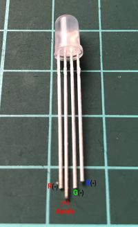
These LEDs need to be bend. I use a Jig to help me bend all the LEDs in the same shape, as shown below.

And the result would be like shown below

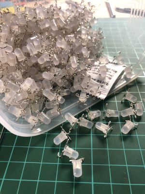
We will need to prepare 512pcs of LED bended with the same way.
LED Matrix
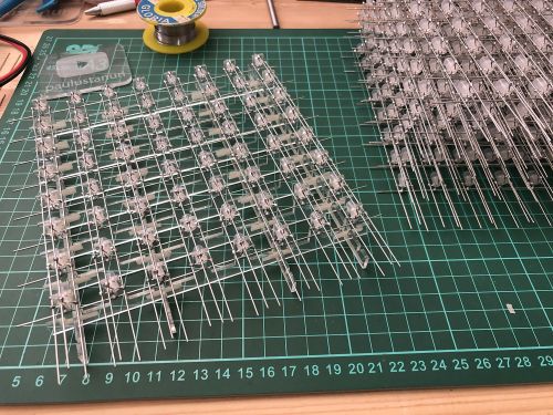
After all the LEDs already been bent, then need to be put together with wires. I used silver color copper wire which usually used for handicraft.
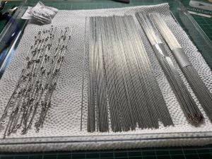
Those wires need to be straightened and cut for about 17cm - 18cm, as shown below.
And LEDs were formed an 8x8 matrix like below.
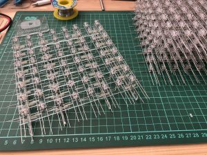
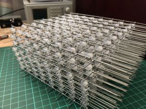
Then we will need to prepare 8pcs of this Matrix. Then we'll able to proceed to the board.
Circuit Boards
There are 3 circuit boards needed for this LED Cube.
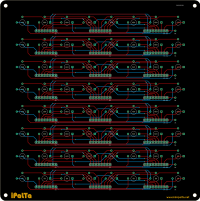
LED Board
This is the top board having all the LEDs soldered onto it.
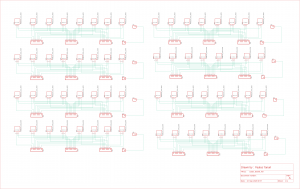
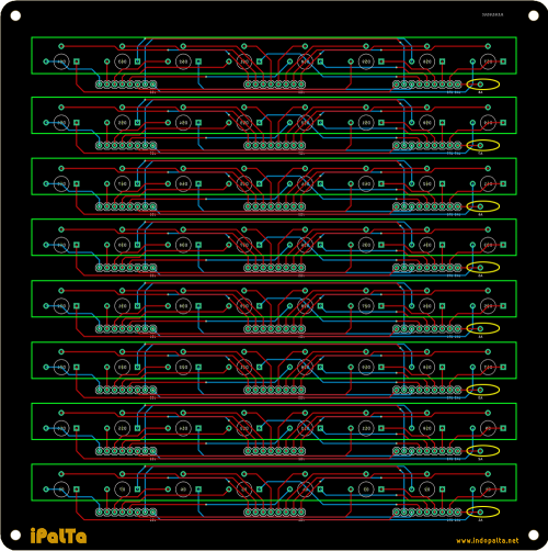
Here are the pictures of the schematic and the board.
And below is the picture with the markings.
The green boxes are the places for the Cathode wires.
The yellow ellipse are places for the Anodes of each layer.
And the rest are for headers to connect this board with the Column Controller board below it.
Also, you will need to solder the male headers first before soldering all the LEDs to the board. Not the way around. Because after the LEDs soldered to the board, you will not able to reach the center.
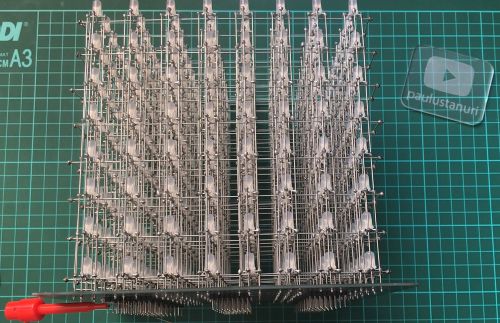
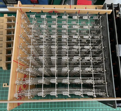
After all the LEDs already soldered, it will looks like the picture below.
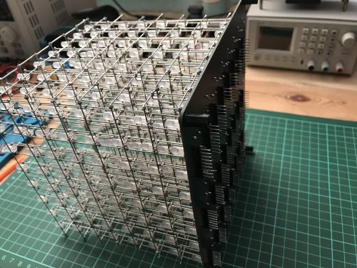
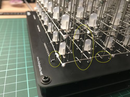
And below is the close up picture for how to connect the Anode wires to the board
Column Controller Board
Is the middle board, mostly consist of SN74HC595 shift register and ULN2803A Transistor Array.
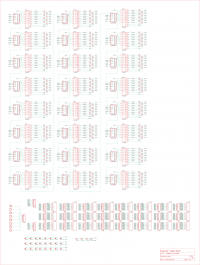
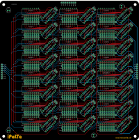
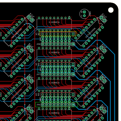
And below is the part of the Column Controller Board.
The parts with the yellow box with code RNx are for Resistor Network 1K Ohm, 9 pins. The first pin pad is the rectangle one.
And the parts with cyan color with code "200" are for 200 Ohm Resistor as much as 8pcs for each Shift Register, place vertically for space.
But later I change to 100 Ohm. So the LEDs hopefully will a bit brighter.
And parts with the green box, with code JRx will be the Header, which will be connected to the LED Board above it.
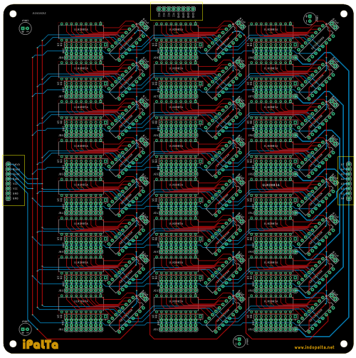
Besides that, there are also 3 headers at the right, left, and top as marked at the picture below, which will connect to Controller Board below it.
The header at the left side will be the shift register control and data pins.
The header at the right side will control the Anode of each layer.
And header at the top will provide connection to VCC and GND to help spread the current.
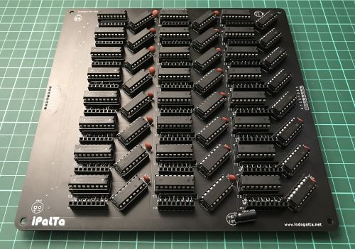
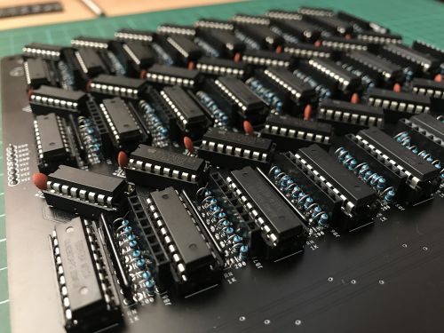
Below are the pictures of the populated Column Controller Board, and the closed up position for better understanding on how the components placed.
Controller Board
This is the main Controller board, consist of 8 MOSFETs, with a shift register with the transistor array and the necessary components to control the power for each layer.
And the main controller of the whole thing, which is the minimum system of ATMega328P-PU, Arduino Compatible.
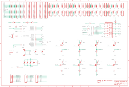
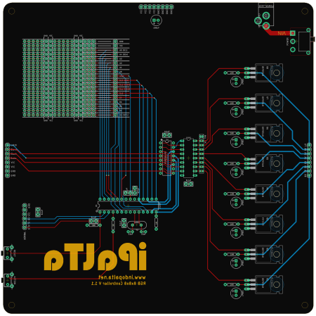
And here is the schematic and the picture of the main Controller board.
And below is the picture of the populated control board..
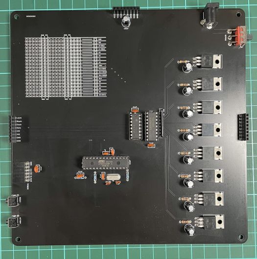
As can be seen at the picture, also from the schematic, there are 2 momentary button at the board.
One is the reset button.
And the second labeled "Action" is connected to INT0 pin, which can be programmed for special needs.
But for now, at the current code, it still doesn't have any line for that purpose.
Components List
This is the list of all the components needed for this project
- IC ATMega328P-PU : 1pcs
- IC Socket 28pin : 1pcs
- Crystal 16Mhz : 1pcs
- Capacitor 22pF : 2pcs
- Capacitor 0.1uF : 31pcs
- Capacitor El 100uF : 13pcs
- Resistor 1k : 1pcs
- Resistor 10k : 2pcs
- Resistor 100R : 8pcs
- Resistor 200R : 192pcs
- IRF9540N : 8pcs
- Resistor Network 1K 9pin : 25pcs
- ULN2803A : 25pcs
- SN74HC595 : 25pcs
- Female Header 1x6 Right Angle : 1pcs
- Male Header 1x8 : 19pcs
- Female Header 1x8 : 19pcs
- Female Header 1x9 : 8pcs
- Male Header 1x9 : 8pcs
- Tactile Button 6x6x5 Right Angle : 2pcs
- SS-12D11G5R SPDT : 1pcs
- Socket DC PCB Mount : 1pcs
- LED 5mm Diffused Color : 512pcs
- M3x6 Black Pan Padded Screw : 4pcs
- M3x5 Male-Female Nylon Spacer : 4pcs
- M3x10 Female-Female Nylon Spacer : 4pcs
- M3x10 Male-Female Nylon Spacer : 4pcs
- M3x7x1 Nylon Flat Washer : 8pcs
- Copper Wire 18cm/pcs : 280pcs
Code
The source code for this LED Cube RGB 8x8x8 also using Kevin Darrah's code, which modified a little to match the schematic I made here. The source code I used can be downloaded from : https://github.com/paulustanuri/PT019_RGB_Cube_888
Available At
The circuit boards with all the components needed are available in a form of a Kit, complete with the jigs needed.
Available at marketplaces below :
- https://bit.ly/TP-PALTA (Tokopedia - Indonesia only)
- https://bit.ly/SP-PALTA (Shopee - Indonesia only)
- https://bit.ly/Tindie-PALTA (Tindie - International)
- https://www.elecrow.com/led-cube-rgb-8x8x8-kit-arduino-compatible.html (Elecrow - International)
The Making Process
For the making process of this cube. Although the video is in Bahasa (Indonesian Language), the English CC is available.
The Jigs
Recently in 2024, I created a new set of Jig for this project. Because the process of bending the LEDs leg is taking quite a lot of time, I tried to make it simpler, but still easy to assembled together.
So here are the new Jigs.
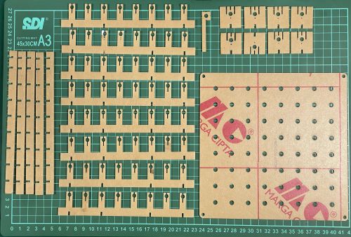
Now, let take more closely look for how to use each of them.
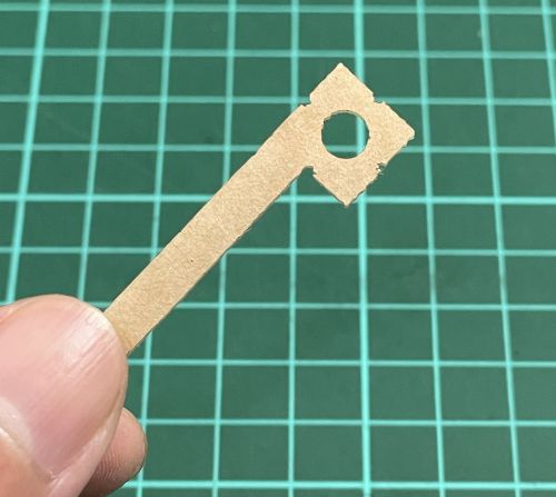
This little one is used to replace the wooden Jig. So with this little Jig, we can bend the LED Legs to the marking positions for each side.
Like the sample shown at the picture below.
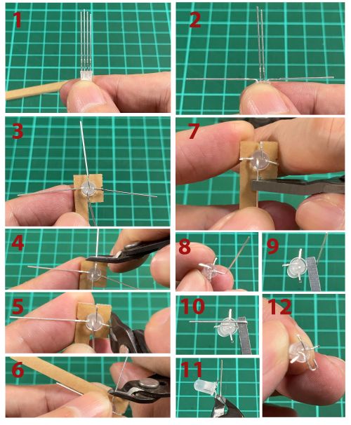
So, now we only have to bend 1 Leg, the Anode. And for the other 3 Legs, we can just cut it accordingly. This will save quite some times.
And now for this other Jig, will be use to arranged 8 individual LEDs in place, and soldered as a pillar.
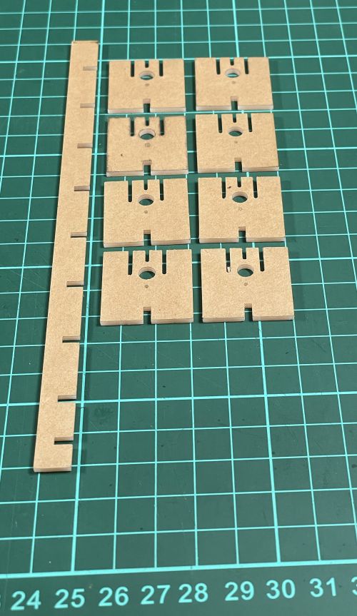
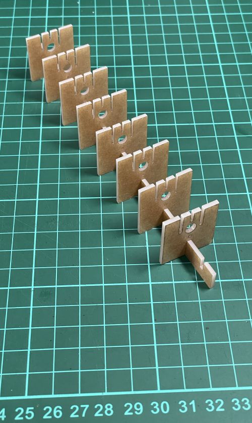
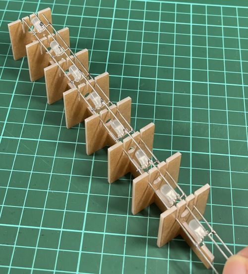
Below is the sample on how to place the LEDs and solder the wire on it.

The Anode leg which are bended will at the bottom, and not soldered here. Using this jig, we will only soldered the other 3 legs.
After soldered, we can slide it downward to take it out of the jig.
For the other shape, beside the bigest one, will assembled like below. And this jig will be used to combine 8 of the Pillars we have created before, and soldered into 1 layer. Using this Jig, we will solder the wire to the Anode of the LEDs.
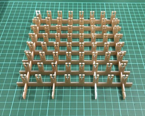
Like this picture below

As for the bigest jig, will be use to help when we will placing all the layers to the PCB.
And when do that, we will need to dissambled the layer jig, and take the lower part and use it with the bigest jig. As shown below
If you need to create the jig on your own, you can use this file for laser cutting. Media:LED_Mount8RGB_all.pdf
Showcase
