LED Cube RGB 4x4x4: Difference between revisions
No edit summary |
No edit summary |
||
| (10 intermediate revisions by the same user not shown) | |||
| Line 5: | Line 5: | ||
What I made here is a PCB version, which all the circuitry were made into 2 separated boards, which then will be connected using headers. | What I made here is a PCB version, which all the circuitry were made into 2 separated boards, which then will be connected using headers. | ||
And these are the 2 boards. | And these are the 2 boards. | ||
<br> | |||
[[File:Boards.JPG|600px]] | [[File:Boards.JPG|600px]] | ||
<br>The left one is for LED Pillars. And the right one is for the controller board. | <br>The left one is for LED Pillars. And the right one is for the controller board. | ||
<br><br> | <br><br> | ||
==Making== | |||
First thing to start when making this LED Cube is to prepare the LED. | |||
At this project, we will use the RGB LED, with Common Cathode type. | |||
<br> | |||
[[File:01_RGB_LEDs_Legs-172x300.jpg]] | |||
<br><br> | |||
And using a jig, we will bend the LED's legs to our need. | |||
<br> | |||
[[File:02_RGB_LEDs_and_Jig-768x697.jpg]] | |||
<br> | |||
As you can see at the picture above, I left the Cathode leg half bend, to differentiate it from the others. This will come handy when we want to solder it to the wire. | |||
<br> | |||
The target is to make the LED like picture below | |||
<br> | |||
[[File:04_RGB_LED_closeup-768x578.jpg]] | |||
<br><br> | |||
And below is the led pillar soldering process. As seen below, the Cathode position of each LED (the one without loop) is rotated clockwise for each LED. | |||
<br> | |||
[[File:LED Pillar Soldering02.jpg|600px]] | |||
<br> | |||
And for another tips, after soldering to the wire, I will cut the 3 wires that connected to Anode (R G B) of the last (bottom) LED, shorter. And left the wire that connected to the last LED's Cathode the only one longer. This will become our position marker when placing it into the PCB. | |||
<br><br> | |||
And here are the circuit boards with all the LED Pillars soldered, and the controller board assembled with all the components. | And here are the circuit boards with all the LED Pillars soldered, and the controller board assembled with all the components. | ||
<br> | |||
[[File:2modules apart.jpg|600px]] | [[File:2modules apart.jpg|600px]] | ||
<br><br> | <br><br> | ||
And here is the picture of the LED Cube RGB 4x4x4 in complete form. | And here is the picture of the LED Cube RGB 4x4x4 in complete form. | ||
<br> | |||
[[File:Assembled.jpg|600px]] | [[File:Assembled.jpg|600px]] | ||
<br><br> | <br><br> | ||
| Line 64: | Line 86: | ||
https://github.com/paulustanuri/PT018_RGB_LED_Cube_V3.1 | https://github.com/paulustanuri/PT018_RGB_LED_Cube_V3.1 | ||
== | ==Available At== | ||
The circuit boards with all the components needed are available in a form of a Kit, complete with the jigs needed. | The circuit boards with all the components needed are available in a form of a Kit, complete with the jigs needed. | ||
[[File:Kit single.JPG|800px]]<br><br> | [[File:Kit single.JPG|800px]]<br><br> | ||
| Line 71: | Line 93: | ||
* https://bit.ly/SP-PALTA (Shopee) | * https://bit.ly/SP-PALTA (Shopee) | ||
* https://bit.ly/Tindie-PALTA (Tindie) | * https://bit.ly/Tindie-PALTA (Tindie) | ||
* https://www.elecrow.com/led-cube-rgb-4x4x4-kit-charliecube-palta-style.html (Elecrow) | |||
==Tutorial== | |||
== | |||
The tutorial to assemble and make this LED Cube can be watch at the video below : | The tutorial to assemble and make this LED Cube can be watch at the video below : | ||
| Line 80: | Line 101: | ||
or you can also check the post here : | |||
<br> | |||
https://www.paulustanuri.com/rgb-led-cube-4x4x4-aka-charliecube-pembuatan/ | |||
==Showcase== | |||
<youtube>og4EE3k7bYI</youtube> | |||
---- | ---- | ||
[ | [{{Server}}/index.php/LED_Cube_RGB_4x4x4 Bahasa Indonesia] | ||
Latest revision as of 06:02, 8 October 2024
Intro
This LED Cube RGB 4x4x4 is actually based on Charliecube designed by Asher Glick, which all the informations are available at https://aglick.com/charliecube.html
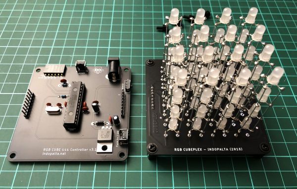
What I made here is a PCB version, which all the circuitry were made into 2 separated boards, which then will be connected using headers.
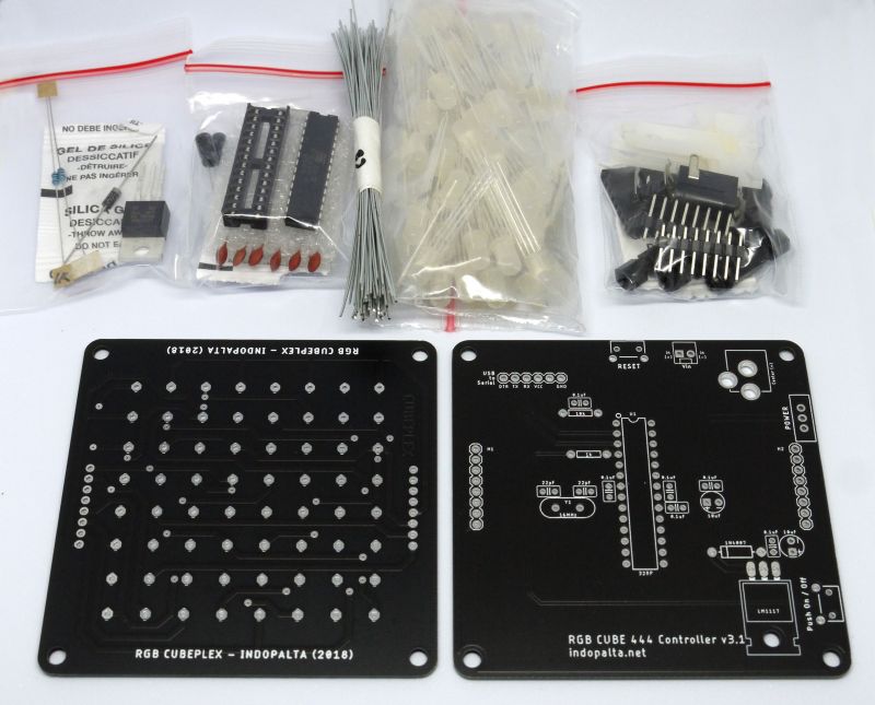
And these are the 2 boards.
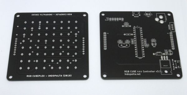
The left one is for LED Pillars. And the right one is for the controller board.
Making
First thing to start when making this LED Cube is to prepare the LED.
At this project, we will use the RGB LED, with Common Cathode type.
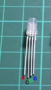
And using a jig, we will bend the LED's legs to our need.
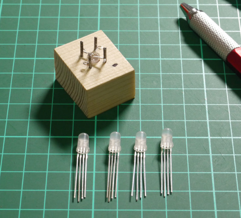
As you can see at the picture above, I left the Cathode leg half bend, to differentiate it from the others. This will come handy when we want to solder it to the wire.
The target is to make the LED like picture below
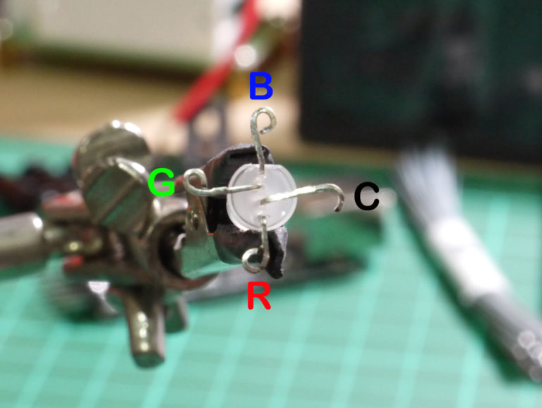
And below is the led pillar soldering process. As seen below, the Cathode position of each LED (the one without loop) is rotated clockwise for each LED.
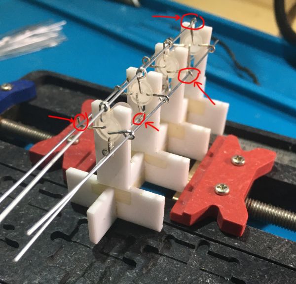
And for another tips, after soldering to the wire, I will cut the 3 wires that connected to Anode (R G B) of the last (bottom) LED, shorter. And left the wire that connected to the last LED's Cathode the only one longer. This will become our position marker when placing it into the PCB.
And here are the circuit boards with all the LED Pillars soldered, and the controller board assembled with all the components.
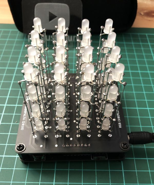
And here is the picture of the LED Cube RGB 4x4x4 in complete form.
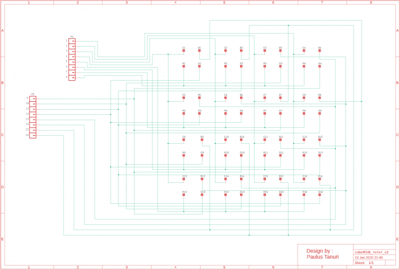
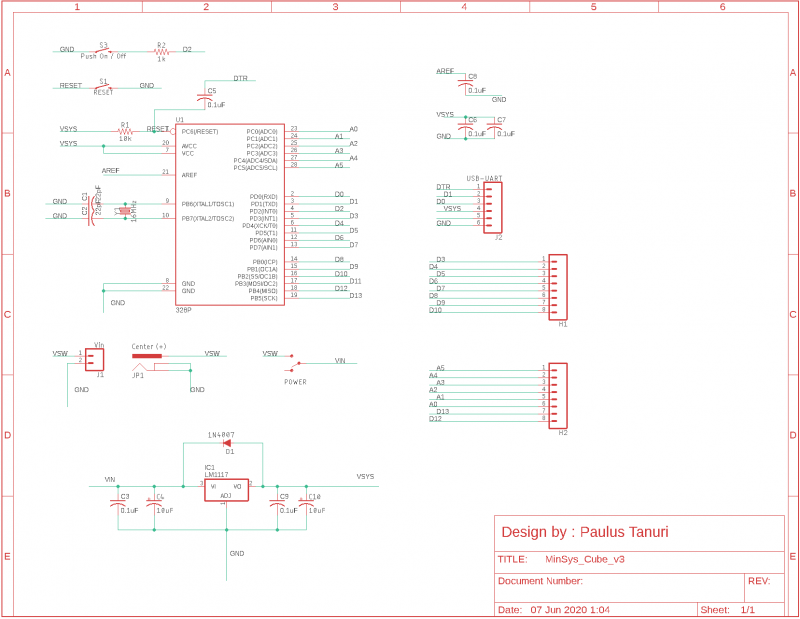
As references, here are the schematic of the 2 boards above.
Komponen
Here are the list of all the components needed for these boards.
- RGB LED 5mm Common Cathode : 64pcs
- Wire : 64pcs
- IC ATMega328P-PU : 1pcs
- IC Socket 28pin : 1pcs
- Crystal 16Mhz : 1pcs
- Capacitor 22pF : 2pcs
- Capacitor 0.1uF : 6pcs
- Capacitor El 10uF : 2pcs
- Resistor 10k : 1pcs
- Resistor 1K : 1pcs
- Pin Header Female 1x6 Right Angle : 1pcs
- Pin Header Female 1x8 Straight : 2pcs
- Pin Header Male 1x8 Straight : 2pcs
- Diode 1n4001 : 1pcs
- Tactile Button 6x6x5 Right Angle : 2pcs
- Mini Slide Switch : 1pcs
- Socket DC PCB Mount : 1pcs
- M3x6 Black Pan Padded Screw : 4pcs
- M3x5 Male-Female Nylon Spacer : 4pcs
- M3x10 Female-Female Nylon Spacer : 4pcs
- M3x7x1 Nylon Flat Washer : 4pcs
- RGB444 Base Board : 1pcs
- RGB444 MinSys Board : 1pcs
- Kabel DC Adaptor Charger USB Male to DC 5.5mm : 1pcs
Code
Source code for this LED Cube RGB 4x4x4 also based on Asher Glick's and modified to work with the schematic used here. Source code are available at : https://github.com/paulustanuri/PT018_RGB_LED_Cube_V3.1
Available At
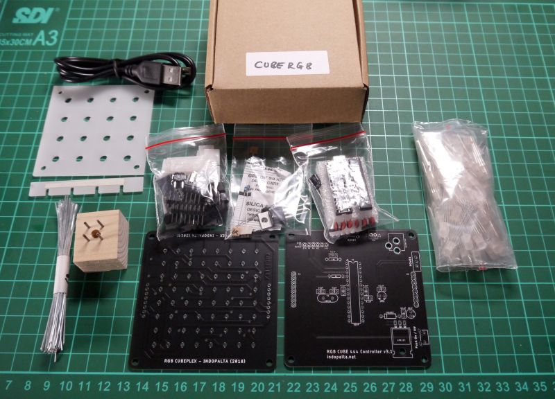
The circuit boards with all the components needed are available in a form of a Kit, complete with the jigs needed.
Available at marketplaces below :
- https://bit.ly/TP-PALTA (Tokopedia)
- https://bit.ly/SP-PALTA (Shopee)
- https://bit.ly/Tindie-PALTA (Tindie)
- https://www.elecrow.com/led-cube-rgb-4x4x4-kit-charliecube-palta-style.html (Elecrow)
Tutorial
The tutorial to assemble and make this LED Cube can be watch at the video below :
or you can also check the post here :
https://www.paulustanuri.com/rgb-led-cube-4x4x4-aka-charliecube-pembuatan/
Showcase
