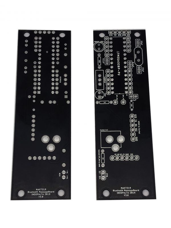
Message Board MAX7219 V3
Intro
This is an Arduino custom board to be used with MAX7219 4in1 Module.
And it already have the pinout for Bluetooth HC-05 or HM-10 connection, or you can use it with another communication module that have same pinout.
Schematic
And here is the schematic for the board, as a reference.
File:M7219 MessageBoard V3 sch.png
Components
Here is the list for all the components you'll need to make this board works.
- IC ATMega328P-PU : 1 pcs
- IC Socket 28pin : 1 pcs
- Crystal 16Mhz : 1 pcs
- Capacitor 22pF : 2 pcs
- Capacitor 0.1uF : 2 pcs
- Capacitor El 10uF : 1 pcs
- Resistor 10k : 1 pcs
- Resistor 220 : 1 pcs
- Resistor 1K : 1 pcs
- Resistor 2K : 1 pcs
- LED 5mm Red : 1 pcs
- Slide Switch : 1 pcs
- Pin Header Male 1x6 Right Angle : 2 pcs
- Pin Header Female 1x5 Straight : 1 pcs
- Resistor 1K : 1 pcs
- Resistor 2K : 1 pcs
And of course you will also need these :
- Module MAX7219 4in1 (as your needs)
- Module HM-10 or HC-05 (you can choose the one you prefer)
Assembling Notes
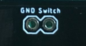
To assembling this board shouldn't be hard. All component's value already printed at the board. But there is a section for 2 pin header, labeled "GND Switch" that could confused you. This is a connecting point for Ground from input to Ground at the board's circuit. You can use this header pin to measure current by connecting it to your Ampere Meter. But in case you not need it, then you can just connect the 2 point using a jumper or just solder it using you resistor leg.
You must connect it, otherwise your board won't turned on since the Ground is not connected.
Software
For the Arduino sketch, can use the sample from MD_Parola, or if you want to use the version I modified, dan be downloaded from :
https://github.com/paulustanuri/PT005_MAX7219_MessageBoard
A little notes if for sending the message from your mobile phone if you using different apps.
Message format should be :
*<CMD>~
Description :
*     : Start code for the message or command

<CMD> : Command code

~     : End code for the message or command
List of CMD :
S : Speed, followed with number (in millisecond)
B : Toggle Brightness between 0-15
R : Reset the Arduino hardware
F : Factory settings
W : Write current setup to EEPROM
M : Show message, followed with the message
J : Toggle Text Justify L, C, R
V : Toggle Invert/Normal
P : Followed with number for delay between in and out(in millisecond)
I : Toggle In Animation
O : Toggle Out animation
C : Followed with number for auto clear message (in millisecond, 0=disable)
Sample :
- To display message "Welcome" . You must send *MWelcome~
How To Get
If you are insterested to get this board, you can visit links to marketplace below : (For now they only available in Indonesia)
- https://bit.ly/TP-PALTA (Tokopedia)
- https://bit.ly/SP-PALTA (Shopee)
- https://bit.ly/Tindie-PALTA (Tindie)
Video
If you wondering how I use these boards, check out video below.

